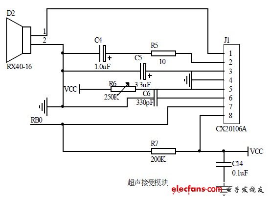
Ultrasonic receiver circuit diagram is shown below:
When the ultrasonic wave propagation in the air, the energy increases as the distance constant attenuation. By experimentally measured, when the detection distance of about 1m, the signal energy has decayed to about 30mv, we need to put the received ultrasonic weak sinusoidal signal amplification, filtering, processing, input to the external interrupt PIC port as a receiver to echo flag. Typically design ideas are first used to amplify LM series of amplifiers, and then filtered, frequency locking, and the circuit input to INT0 generates an interrupt. The advantage of this method is that you can lock the frequency needed to prevent outside interference ultrasonic other frequencies, but the disadvantage is that integration is not high, the design and welding more complicated. So this paper uses Sony's CX20106A infrared remote control receiver integrated chip that can be used for ultrasonic processing circuit, which integrates the amplification, limiting, bandpass filtering, peak detection, shaping, and compare functions, with high sensitivity and anti- interference [5] .CX20106A chip 7 pin PIC microcontroller connected to INT0, when not received ultrasound, 7-pin output high 4.1v or so, do not interrupt; When receiving consistent with a center frequency of 40KHz When ultrasound or similar, they produce a low jump.
When detected bottom transitions, the first falling edge of the signal input to the INT0 as an external interrupt signal, and then close the timer T1 and read the count value of T1, the next step of time and distance calculations.

Figure system transmitter circuit.
No comments:
Post a Comment
Please comment