As shown below, STM32F103F103 and four-wire resistive touch screen directly through its own I / O port to connect to realize the touch screen controller functionality. Which PA8, PA9, PA10, PA11, respectively, as the control end of the four transistors by controlling the transistor off, to control the four-wire touch screen Y +, Y-, X +, X-.PA1, PA2 are two A / D converter channel connected, respectively, and X + Y + is used to calculate the X and Y touch point coordinates. PA3 internal interrupt the connection if the touch screen is used to detect a touch action. Touchscreen usual running, so that PA8, PA9, PA11 output 0, PA10 = 1, i.e. only allow VT2 conduction.When a touch action, D1 is turned on, an interrupt signal to PA3, STM32F103 received set PA8 = 1, immediately after conducting an interrupt request VT1, so that the Y +, Y- direction of the voltage application, and start the A / D converter Channel PA2, by entering the X + voltage to calculate the Y coordinate of the touch point, then empathy make PA8, PA10 is 0, PA9, PA11 is a start A / D converter channel PA1, by entering Y + voltage to calculate the touch point X coordinates.
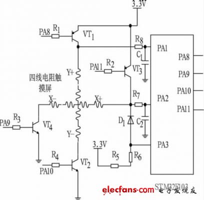
STM32F103 and four-wire resistive touch screen interface circuit
No comments:
Post a Comment
Please comment